In this post we will be learning about Retaining Walls. This post is divided into 4 parts. First we will learn about general types of retaining walls and its components. After that we will see types of failures in a retaining wall, then we will see general forces and behaviour of retaining walls, and lastly typical reinforcement in a cantilever retaining wall. So go through the full post to have a better idea about retaining walls.
What is a Retaining Wall?
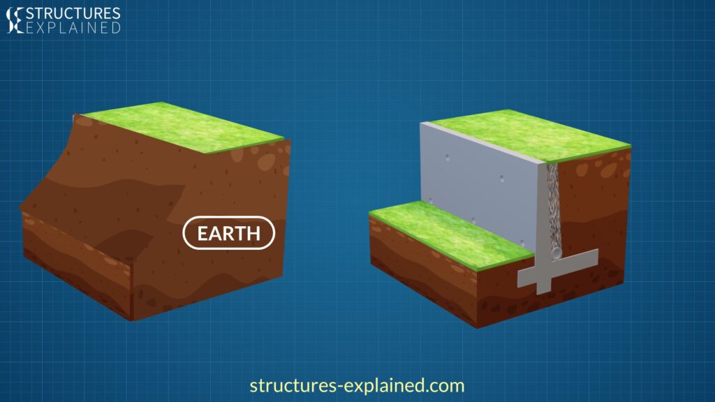
Retaining walls are used to hold earth or any other material. It prevents soil from taking its natural position and makes area above and below it usable.

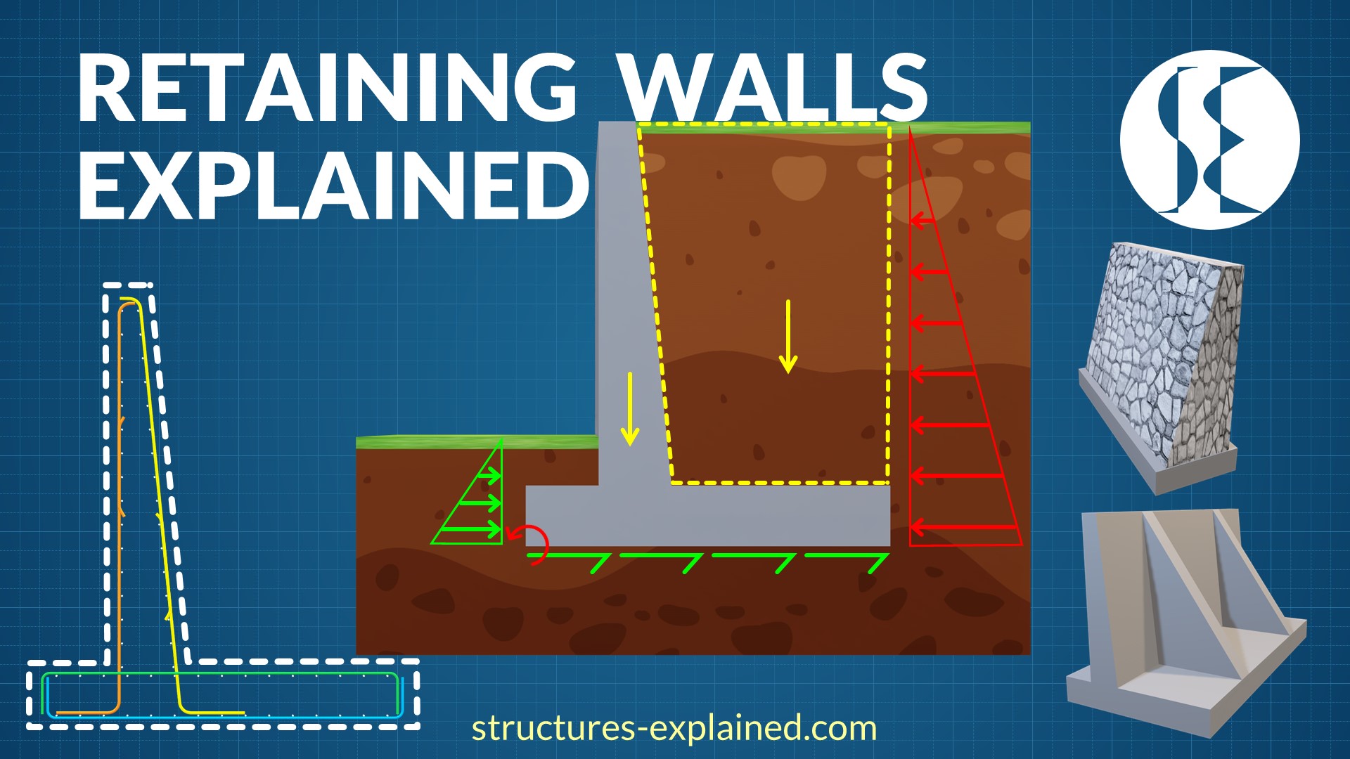
The wall has basically 3 parts. Stem, Toe Slab and Heel Slab. Toe and Heel slab make up for the foundation of the wall. Some walls have a key provided in footing to prevent it from sliding.

The stem may be provided with drain holes with slope for the water drainage. Similar sloping perforated pipe may be provided below the same for water drainage. The soil behind the stem can be coarse aggregates so that water percolates and exits via drains.

The portion of wall in contact with the soil is usually provided with some kind of waterproofing. This waterproofing can be in the form of EPDM membrane or waterproofing boards.
Types of Retaining Walls
1. Gravity Wall

Type of a retaining wall depends on its use. First type is a Gravity Wall which retains soil by its own weight. Gravity wall is of a bigger size and usually built by stone masonry and rarely in plain concrete.
2. Cantilever Wall

Cantilever Wall is the most common type of retaining structure. It is usually used for retention height up to 8 meters or 25 feet.

The 3 components, which are stem, toe, and heel act as one-way cantilever slabs. The stem acts as a vertical cantilever under lateral earth pressure. The heel acts as a vertical cantilever under the action of net weight of the retained earth and the toe acts as a cantilever under the action of net soil pressure.
The resulting deformed shape would look something like in the above picture. The main reinforcement resisting the tension forces will be provided in ‘red marked’ regions as the concrete is weak in tension.
3. Counterfort Wall
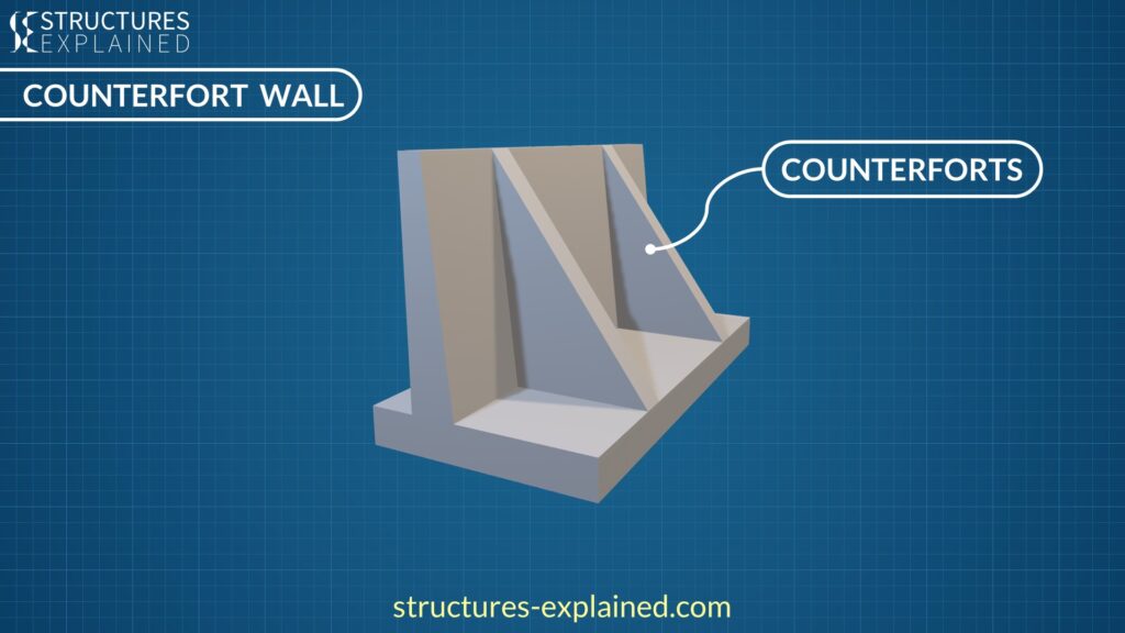
Counterfort Walls have supports called ‘counterforts’ connecting stem and heel slabs. The counterforts are concealed in the retained earth. These walls are provided where retention height is more than around 7 meters or 23 feet.
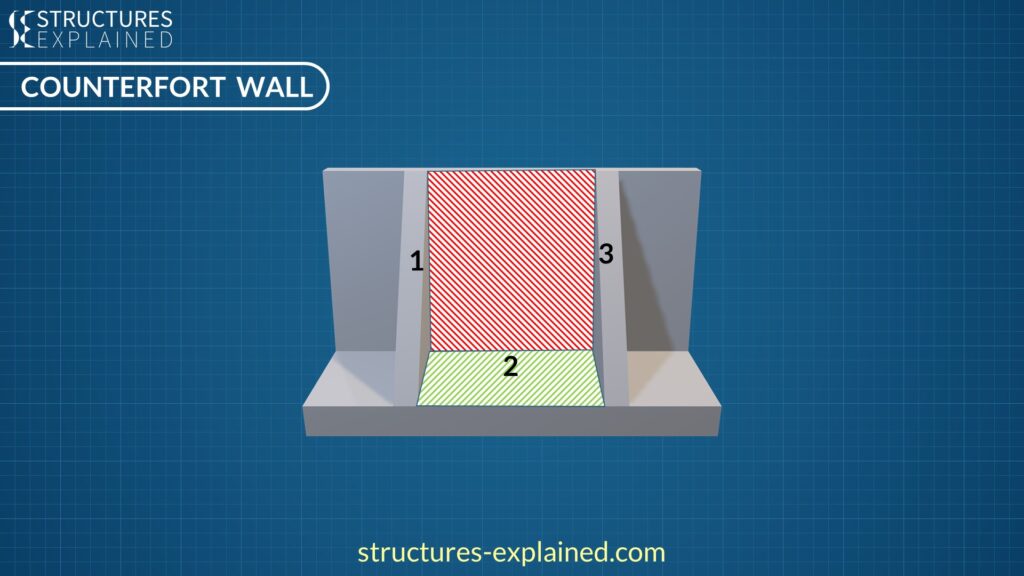
The counterforts subdivide the Stem and heel into rectangular panels. These panels are now supported on 3 sides and free at one edge.
4. Buttress Wall

Buttress Walls are similar to the Counterfort walls but the supports are now on the toe side and not buried in earth. Between the two, counterfort and buttress, Counterfort wall is preferred as it provides usable space in front of the wall and looks clean. In terms of efficiency and economy Buttress wall is preferred.
5. Basement Walls and Abutments
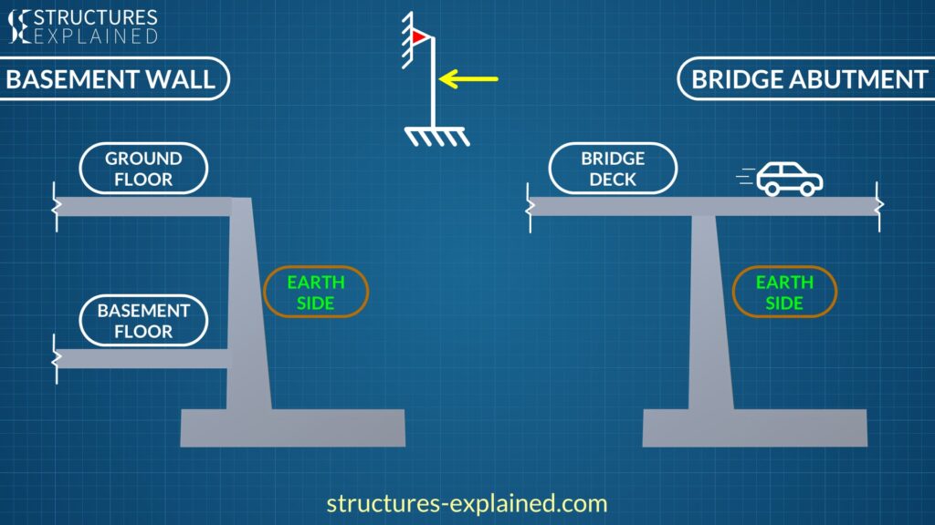
Fifth type of retaining wall is restrained on the top and can be found in Buildings as Basement walls and in bridges as Abutments. In both these cases, the stem is supported by floor slab in Buildings and Deck in bridges. For the analysis part, the stem is considered as a beam fixed at the base and simply supported or partially restrained at the top.
Types of failure of a Retaining Wall
Now let us understand failure modes of a cantilever retaining wall.
1. Failure by Overturning
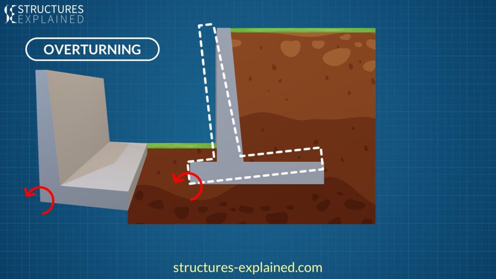
In this failure mode, the toe will act as centre of rotation and the wall would deform something like in the above image. In absence of toe, the footing base below the stem will act as centre of rotation.
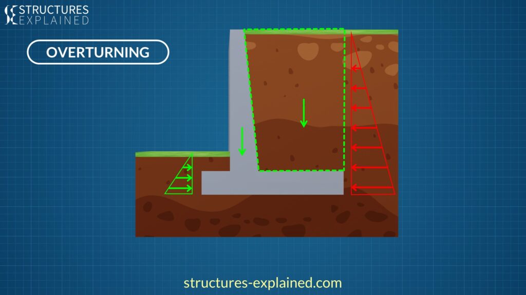
All the lateral pressures will act as overturning forces while the weight of the wall and soil on the heel will act as stabilizing forces.
2. Failure by Sliding

Second kind of failure is by sliding. All the lateral forces try to slide the wall. The resistance against sliding is mainly provided by the friction between the base slab and the soil below it. The frictional force is given by ‘µ’ times R where mu is the static friction coefficient between soil and concrete, and R is the resultant soil pressure.
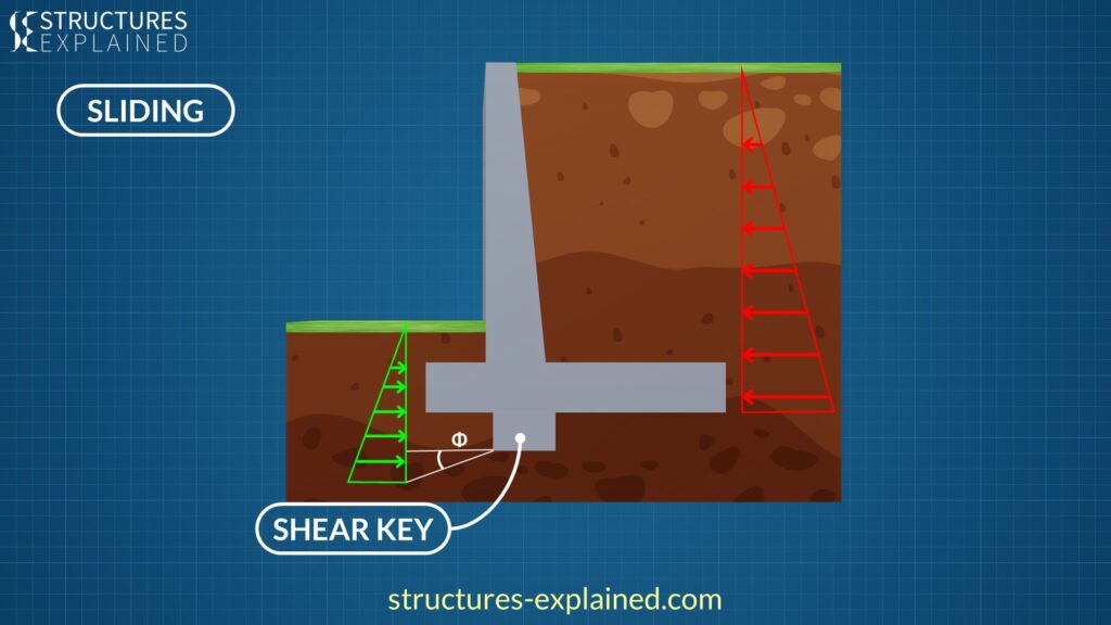
When the lateral pressures are high and the wall fails in sliding, a shear key can be introduced to increase the sliding resistance. The position of the shear key is decided in such a way that the flexural reinforcement from the stem can be extended straight into the shear key, and it can create maximum counter pressure. The pressure generated on the shear key resists the lateral forces.
3. Failure by Bearing Pressure
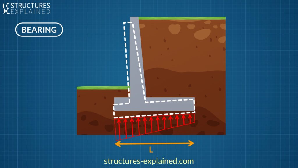
Third kind of failure occurs when the soil below the wall fails in bearing pressure. A soil can bear a certain amount of allowable pressure which is found by geotechnical study. Hence the width ‘L’ of the base slab must be adequate to distribute the vertical reaction.
Forces on a cantilever Retaining Wall
Active Pressure
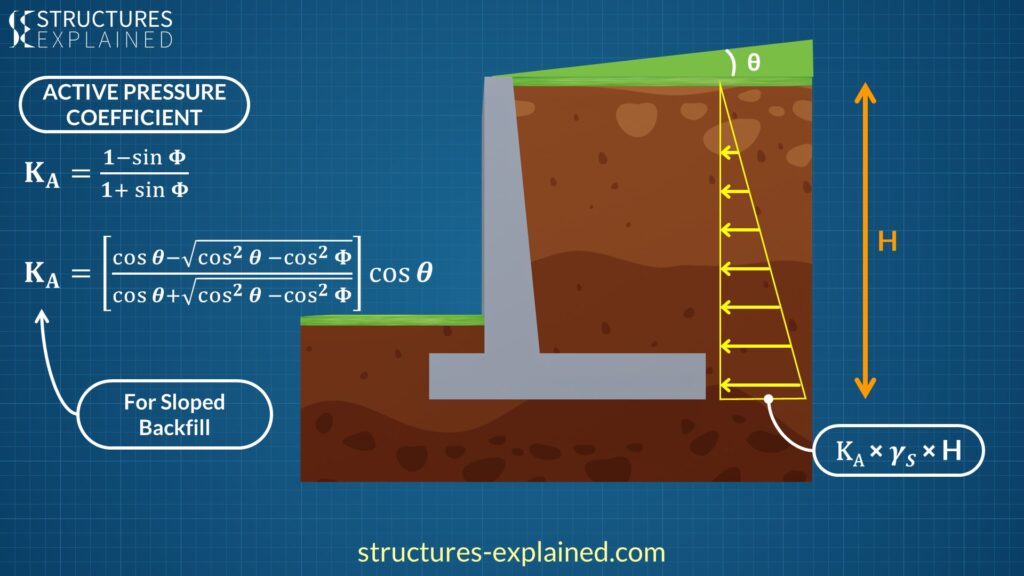
Now let us see the forces which act on a simple Cantilever Retaining wall. First let us assume a flat backfill with no additional load. The soil will apply lateral pressure which will vary with the depth of the soil, which means, top of the wall will bear no pressure while bottom of wall will bear maximum pressure.
This pressure is called active pressure, or in short ‘PA’ as it is actively trying to push the wall along it. The intensity of the pressure at bottom will be KA × 𝜸𝑺 × H. In this expression ‘H’ is the total height of the backfill, ‘𝜸𝑺’ is the unit weight of the soil. Here, KA is the active pressure coefficient based on Rankine’s theory and is calculated via the expression given in above image. Here angle ‘Φ’ is the angle of shearing resistance or angle of repose for the soil.
When the backfill is sloped, the expression changes to the second equation in the image, where additional angle ‘θ’ is the angle of inclination of the backfill.
For a typical granular soil such as sand, ‘Φ’ is 30 degrees which makes KA as 1/3.

This Pressure PA will act at the centroid of the pressure intensity triangle which is at a distance of ‘H/3’ from the base. The value of this force will be the area of triangle which is half times base times the height.
Passive Pressure

Passive pressure acts from the toe side and helps the retaining wall. The coefficient of passive pressure ‘KP‘ is calculated by the expression in the above image, which comes out to be ‘3’ for granular soil with ‘Φ’ of 30 degrees. This pressure is generally not included in design calculations hence making design conservative.
Surcharge
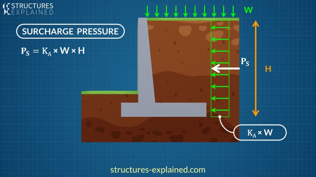
Surcharge is an active pressure which can come from various means such as vehicular traffic, construction activities or any other live loads. Let us consider this surcharge having intensity of ‘W’ Newtons per meter square or pound per square foot, and uniformly distributed. This pressure will act laterally on the wall with an intensity of ‘KA × W’. The force due to this surcharge is the area of the rectangle which is ‘KA × W × H’.
Water and Submerged Soil Pressure
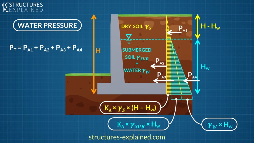
Next Force which acts on the wall is from the water present behind it. This case is a bit complex, so let us simplify it slowly. When water does not have an escape route, it will get accumulated and apply pressure on the wall. Let us consider the height till which the soil is submerged in water as ‘HW‘. The remaining dry soil will have a height of ‘H – HW‘ where ‘H’ is the total height.
The dry soil will have a unit weight of ‘𝜸𝑺‘ and the submerged soil will have a unit weight of ‘𝜸𝑺UB‘
Let us make the pressure diagrams one by one. First will be the pressure from dry soil, let’s call it ‘PA1‘. This dry soil will act as a surcharge for the remaining portion of the wall. Let’s call this pressure ‘PA2‘. The maximum intensity of the pressure will be ‘KA × 𝜸𝑺 × (H – HW)’
Now let us talk about submerged portion. Here the first pressure, let’s call it ‘PA3‘ will come from submerged soil and will have an intensity of ‘KA × 𝜸𝑺UB × HW’
The water pressure in this area, let’s call it ‘PA4‘, will have an intensity of ‘𝜸W × HW’. All the forces can be added by finding the area under them to calculate total force acting on the wall, hence total pressure is given by PT = PA1 + PA2 + PA3 + PA4
The water pressure can be avoided by providing proper drainage facilities like holes and drains. Failure to do this can result in building up of large amounts of water pressure.
Typical Reinforcement in a Retaining Wall
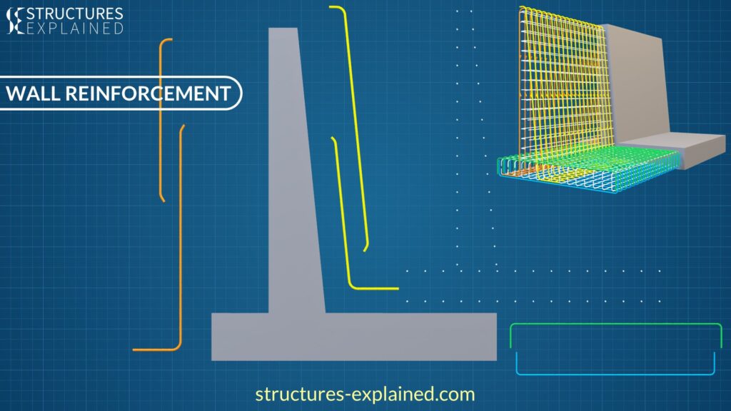
Now let’s look at the typical reinforcement in a cantilever retaining wall. The wall is provided with reinforcement to resist various kinds of stresses produced in it.
The reinforcement has a clear cover on the higher side as the wall is in contact with the soil.

The main reinforcement in the stem is as shown above and is distributed with equal spacing along the length. The bars are lapped if required and have a 90-degree hook at the end. If the wall has a key, the main reinforcement is extended into the key.

On the compression face we also have reinforcement which is extended into the base slab with 90-degree hook for sufficient anchorage. These rebars can also be lapped if required.
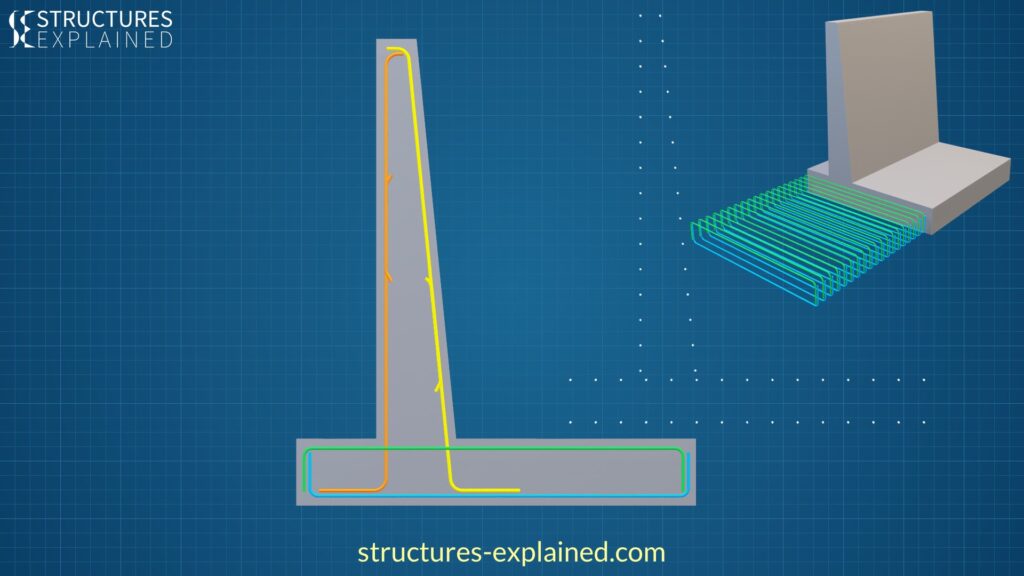
The base slab has reinforcement at both, top and bottom faces to resist the tension and compression forces. They have a 90-degree hook for sufficient anchorage.
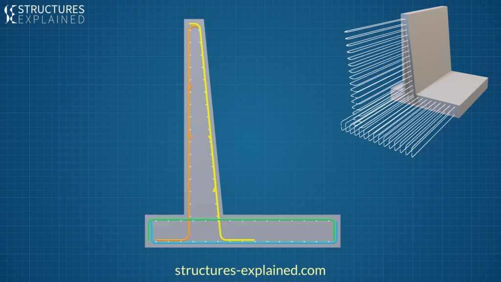
Distribution bars are spread throughout the stem and base slab to resist stresses and hold the main reinforcement in place.
Also read 👉 Structural Elements of a Reinforced Concrete Building
Watch in Video format 👇

Pingback: rybelsus cost
Pingback: purchase clomid online
Pingback: cialis 2.5
Pingback: sildenafil oral jelly 100mg kamagra
Pingback: viagra pfizer 50 mg online
Pingback: cialis online
Pingback: ginseng for libido in men
Pingback: viagra 25 mg tablet
Pingback: canadian viagra 100mg
Pingback: cialis 20
Pingback: cialis super active
Pingback: sildenafil 50 mg coupon
Pingback: cialis pills 20mg