In this post we will learn about shear forces and shear stresses and how they act in structures. Later in the post we will know how shear forces act on a beam and measures to resist shear force.
Shear Force Definition
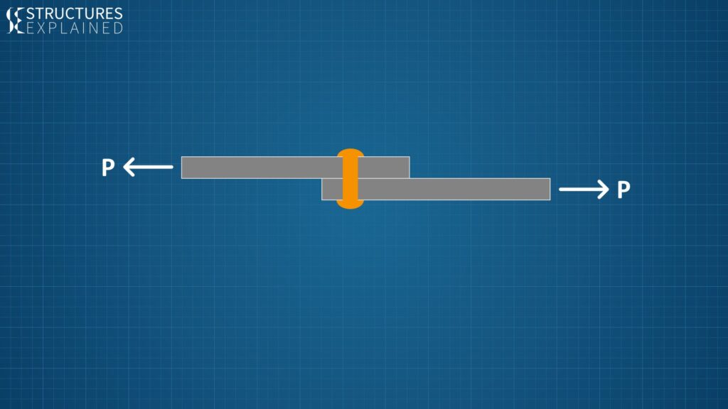
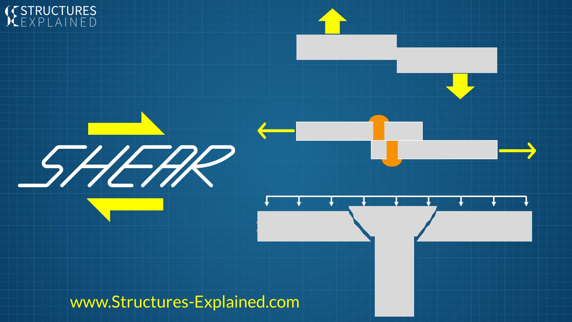
In mechanics, shear forces are unaligned forces pushing one part of a body in one specific direction, and another part of the body in the opposite direction. Assume two metal plates attached to each other by a rivet. If we apply a force ‘P’ on each plate in the opposite direction, there will be some stresses generated at the cross section of the rivet. If the rivet is unable to withstand that force it will break along the cross-section.
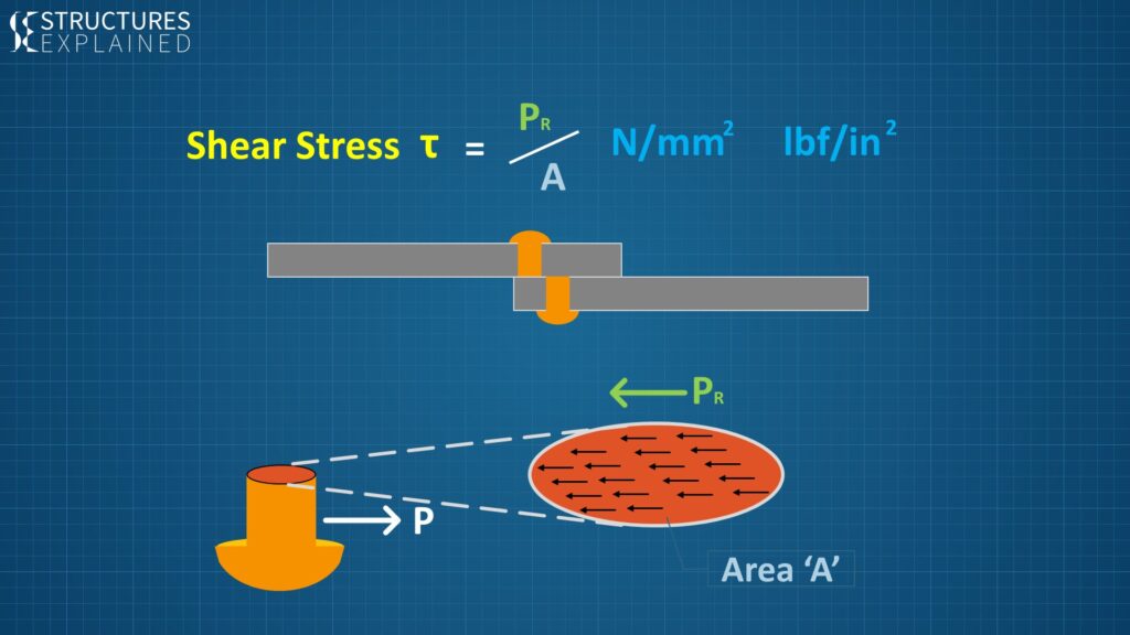
So in the above arrangement force ‘P’ is the shearing force and the stresses it produces in the cross section area is the shear stress. So shear stress in this arrangement will be force resisted by rivet ‘PR’ divided by cross sectional area of rivet ‘A’.
Shear stress is generally denoted by Greek letter tau ‘t’. Unit of shear force is Newton (N) or Pound force and the unit of shear stress is Newton per mm square (N/mm2) or pound force per inch square (lbf/in2).
Shear Force in Daily Life
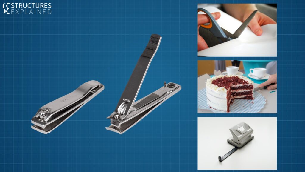
Now let’s see some real life examples where we can use share force.
• Cutting of paper by scissors
• Cutting a cake by a knife
• Punching holes in the paper by paper punching machine
• Cutting nails by a nail cutter.
All these actions make use of shear forces.
Shear Force / Stress in Structures
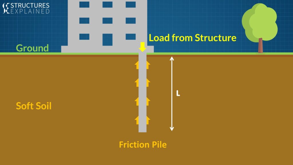
Now let’s see where shear forces are generated in civil structures. Let’s assume a construction site which has soft soil for the foundation. For this site, Pile Foundation is used for building. Assuming a single pile for representation purposes, the load from the structure will pass to the ground by friction piles. Friction or shear forces between soil and pile foundations keep the building standing still. If the length of the pile is not sufficient enough to resist the building forces then Foundation will fail.
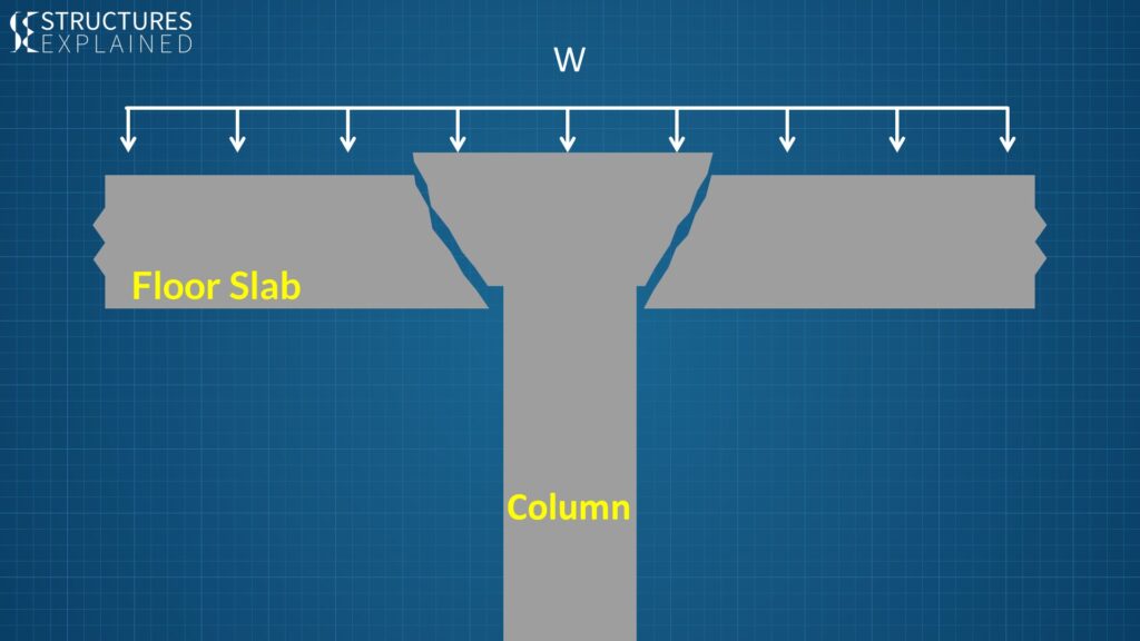
Now let’s assume a concrete floor slab in a building supporting on a column load with load ‘w’. The column will punch into the slab if slab and reinforcement in it are not able to resist the shear stresses.
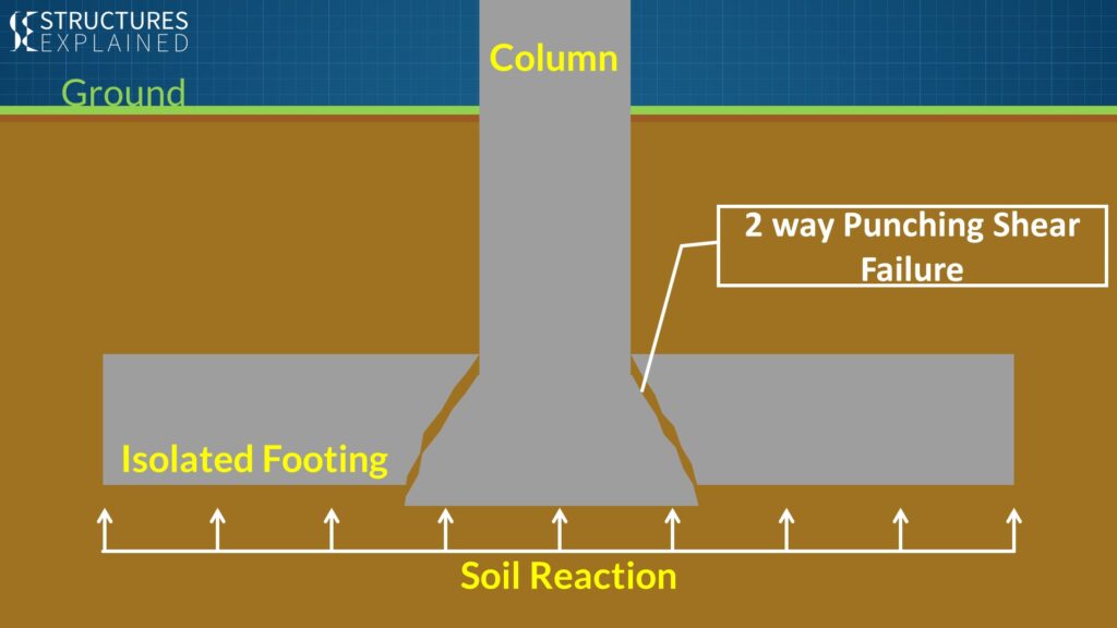
Similar thing will happen in an isolated footing resisting the soil reaction from the bottom if it is inadequate to resist the shear forces. These two examples of failure modes in slab and footing are called two way punching shear failures.
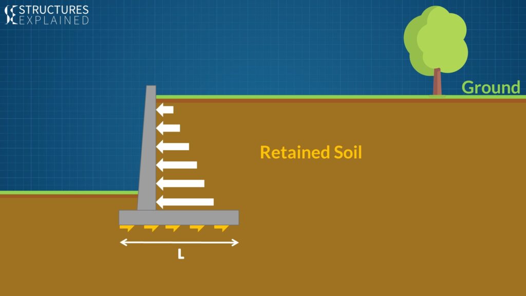
Now let’s see how shear forces are acting on a retaining wall. The retained soil behind the shear wall will try to slide the wall along with it. The frictional force generated between the wall bottom and ground below will resist it hence saving it from sliding, but if the length of the wall footing is not enough the wall will fail in sliding.
Shear Force Diagram (SFD)
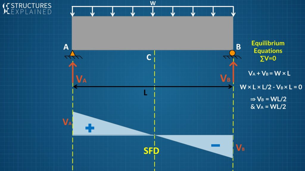
Now let’s see how shear force varies along a concrete beam loaded with uniform load ‘w’ and supported on points A and B. Assuming the beam to be massless, if we write the equilibrium equations along vertical direction, we will get the support reactions ‘Va’ and ‘Vb’ as WL / 2. If we want force at the centre of the beam ‘C’ by assuming half of the beam, we get ‘zero’ reaction at the point ‘C’ as ‘Va’ will cancel out WL / 2. With this information we can draw the Shear Force diagram with ‘Va’ and ‘Vb’ at extremes and ‘zero’ force at centre.
Shear Force Sign Convention
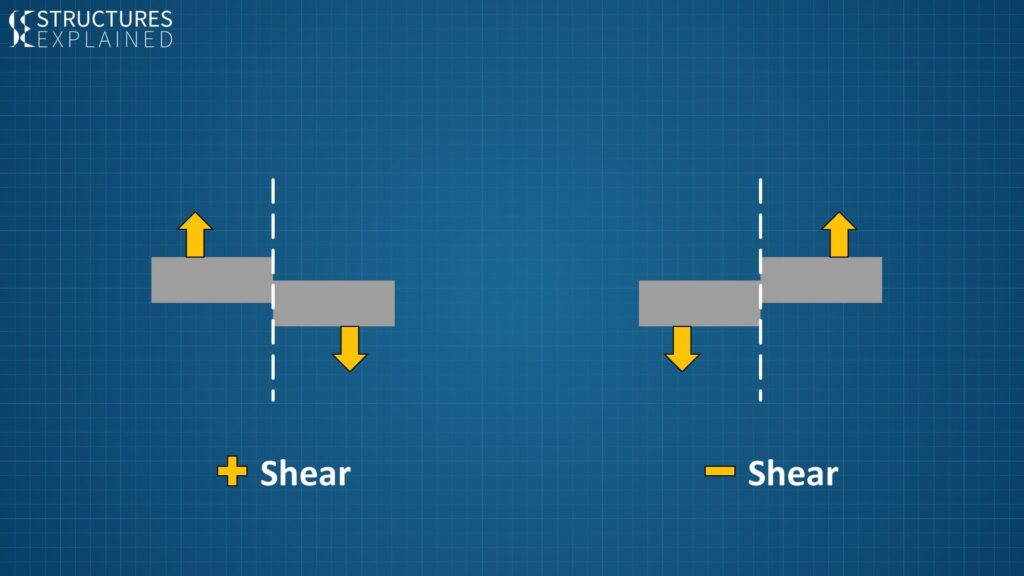
You will wonder how positive and negative signs are assigned on this diagram. If a section has upward force on left and downward force on the right it is denoted by a positive sign and if section has downward force on the left and upward force on the right it is denoted by negative sign.
Shear Cracks in Concrete Beam

Now let’s see what kind of cracks are produced in the concrete beam due to flexure and shearing stresses. Let’s assume a concrete beam loaded with line load ‘w’. There are basically three kinds of crack produce in a concrete, which are:
1. Flexural cracks or cracks due to bending of the beam
2. Flexural + shear cracks which are caused due to combination of bending and shear forces
3. Lastly shear cracks which tend to come up near the support due to shear forces.
Shear Reinforcement
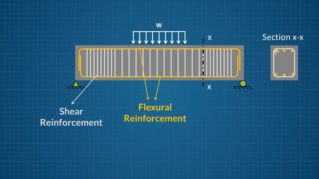
To arrest these cracks reinforcement is provided in the beam. The longitudinal reinforcement also called as flexural reinforcement prevents the bending of the beam hence arrest the cracks due to flexure and flexure plus shear.
The shear reinforcement in the form of stirrups is provided to make the beam stronger in shear and prevent the shear cracks. Note that shear stirrups are closely spaced near the supports as shear higher near the supports.
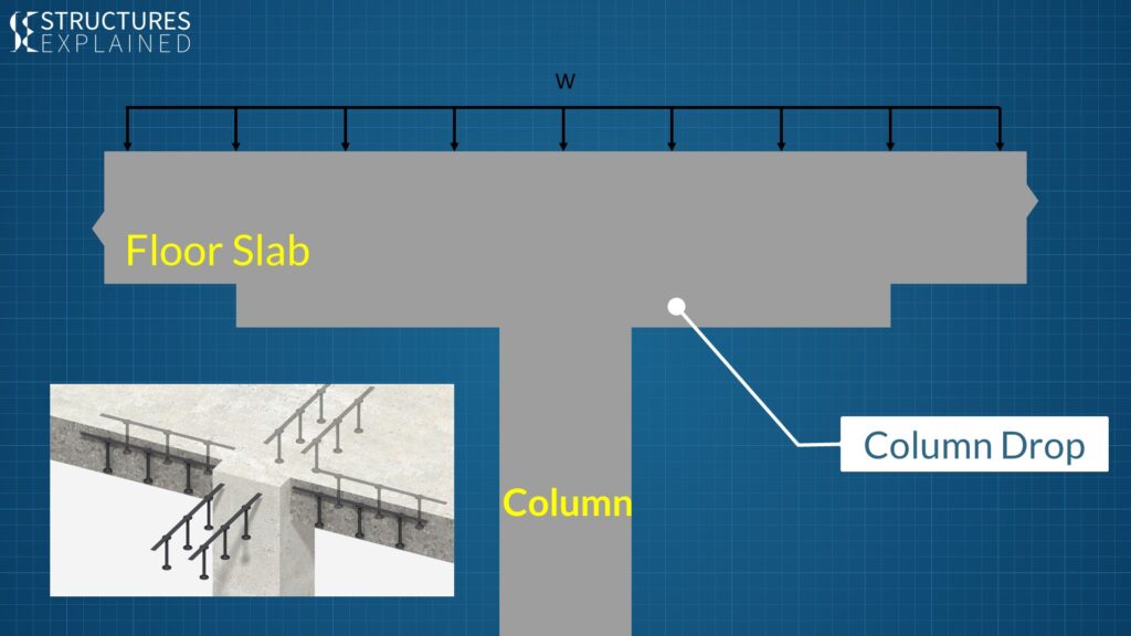
Going back to our floor slabs and column illustrations, the two way punching shear failure can be avoided either by providing stirrup reinforcement or shear strips or by increasing the depth of slab under the column, also called as column drop. Similarly, 2-way punching shear failure in an isolated footing can be avoided by providing shear reinforcement or increasing the depth of the footing.


Pingback: rybelsus tablets
Pingback: clomid medicine
Pingback: best price for viagra 100mg
Pingback: 50 mg sildenafil citrate
Pingback: average cost of cialis
Pingback: best online cialis
Pingback: ginseng extract for men
Pingback: 20mg generic cialis pill
Pingback: 25 mg viagra price
Pingback: buy viagra 100mg
Pingback: buy viagra 50mg online
Pingback: order cialis online