In this post, we will be learn about Torsion as a force and how it acts on structural members and building structure.
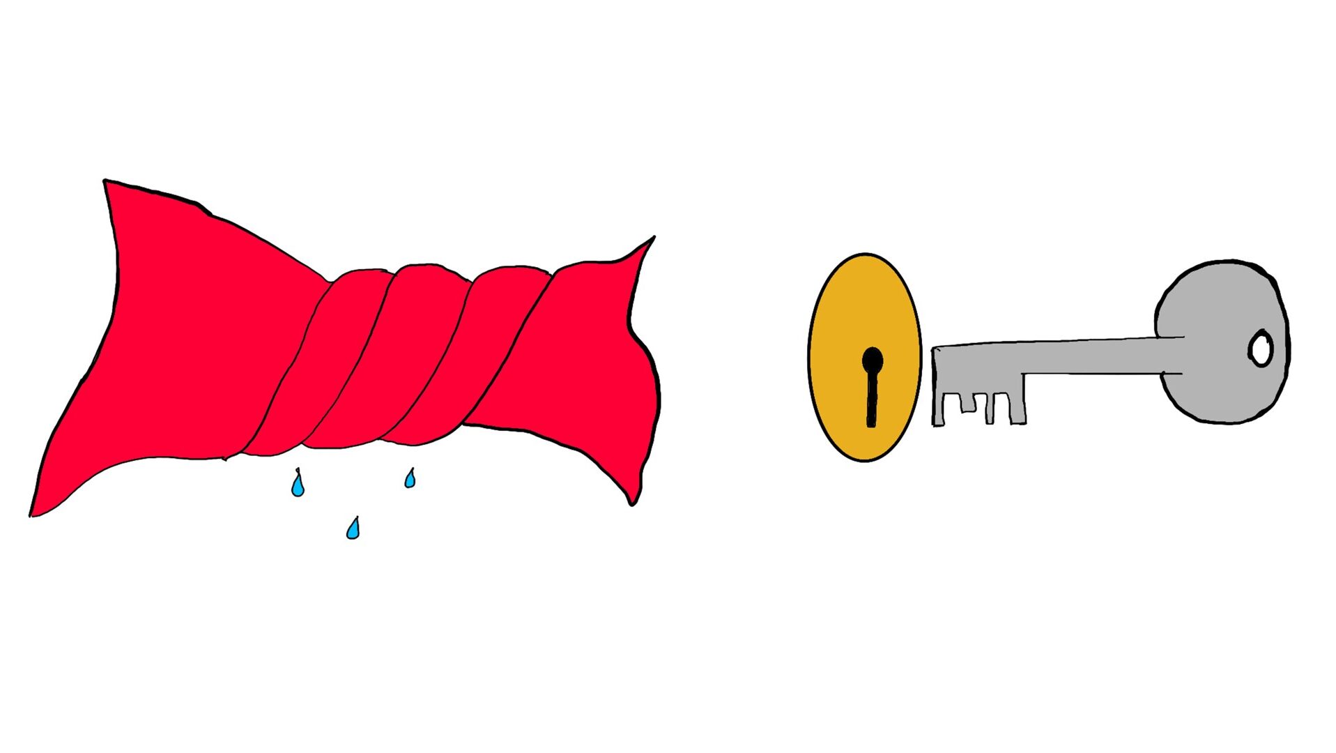
In daily life we experience many instances where we apply torsion to the objects. Opening a door lock is one such moment in which we rotate the key along its main axis to open the lock. The force, also called as torque is the main player in this scenario.
Next, we look at wrenching of clothes to remove water from them. The force at both the ends is applied in opposite direction to twist the cloth resulting in draining of water. These examples show torsion in action in day to day life.
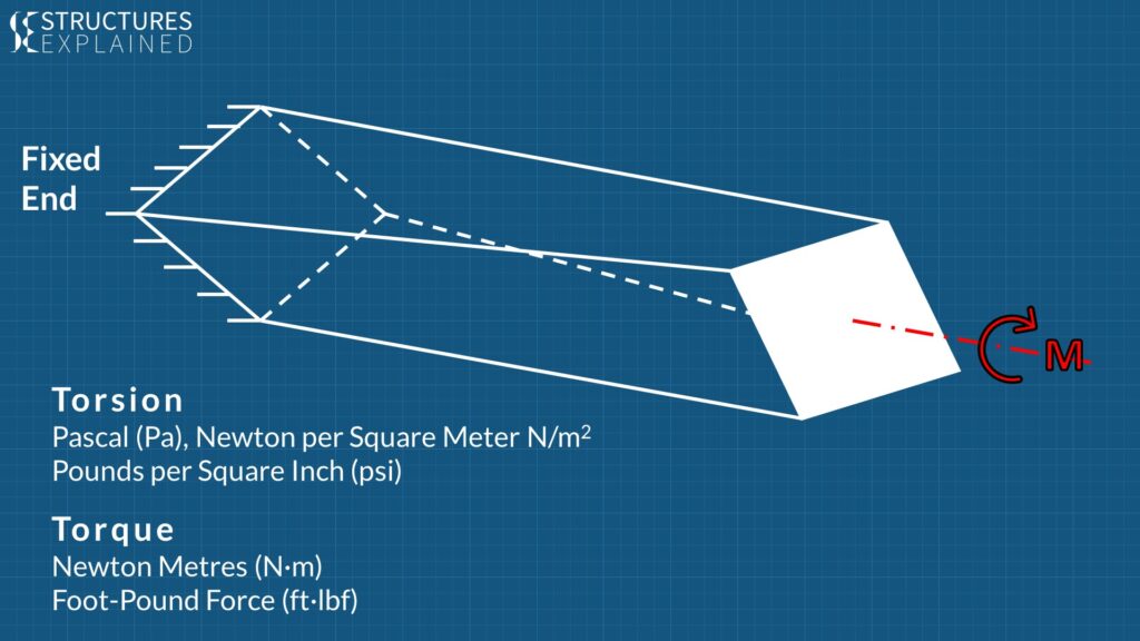
Structural elements in a building or a bridge also undergo this force all the time. Let’s consider a rectangular concrete beam fixed at one end and applied with a moment or Torque along the main axis of the beam at other end. The fixed end will resist the rotation, but the free end will rotate creating stresses in the cross section of the beam.
From the above illustration we can say that Torsion is a vertical moment acting on main axis of beam creating shear stresses in it.
Torsion is expressed in either the Pascal (Pa), an SI unit for newtons per square metre, or in pounds per square inch (psi) while torque is expressed in newton metres (N·m) or foot-pound force (ft·lbf).

When the beam is revolved around its axis there will be friction between adjacent sections along the beam and the sections will try to resist the rotation.
This will produce stress in the cross section which will be radially increasing from center to the periphery of the section. Highest stress will be on the outermost portion of the beam and least in the centre.
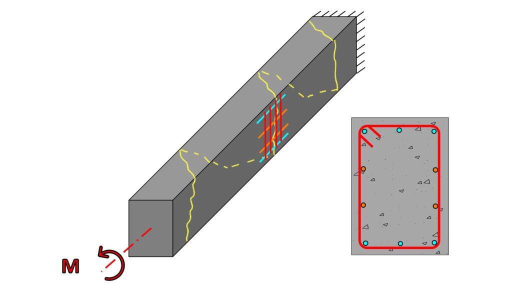
This stress will cause a concrete beam to produce cracks in it which will occur at an angle of 45 degrees from cross section of beam. To resist this stress a combination vertical and longitudinal reinforcement will be required to arrest the cracks.
The longitudinal reinforcement in top and bottom, shown above in Blue, run along the beam and the vertical reinforcement also called as stirrups, shown in red are distributed in whole beam. For beams in torsion the stirrups must be closed and having 135 degree hooks. Side bars are also provided for resisting torsion if needed by design, which are shown here in orange. The combined action of these reinforcement and internal resistance of concrete counter the torsion forces and cracks produced in the beam.
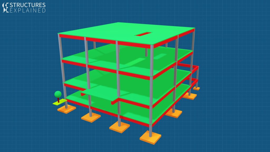
Now let us see various scenarios in a concrete framed structure where beams are subject to torsion. The model above represents a 3 storied reinforced concrete framed structure with normal slab, beam, column and footing arrangement. So, in this 3D view we can see orange coloured isolated footings, grey coloured columns, red coloured beams and green coloured slabs.

First comes the perimeter beams of a building which run all around the building. These beams are loaded from only one side hence are subject to torsional forces. The beams which are curved in plan are also acted by torsional forces.

Then comes the beams which are near opening or cutouts in the slab. These beams are also loaded from one side hence attract torsional forces.
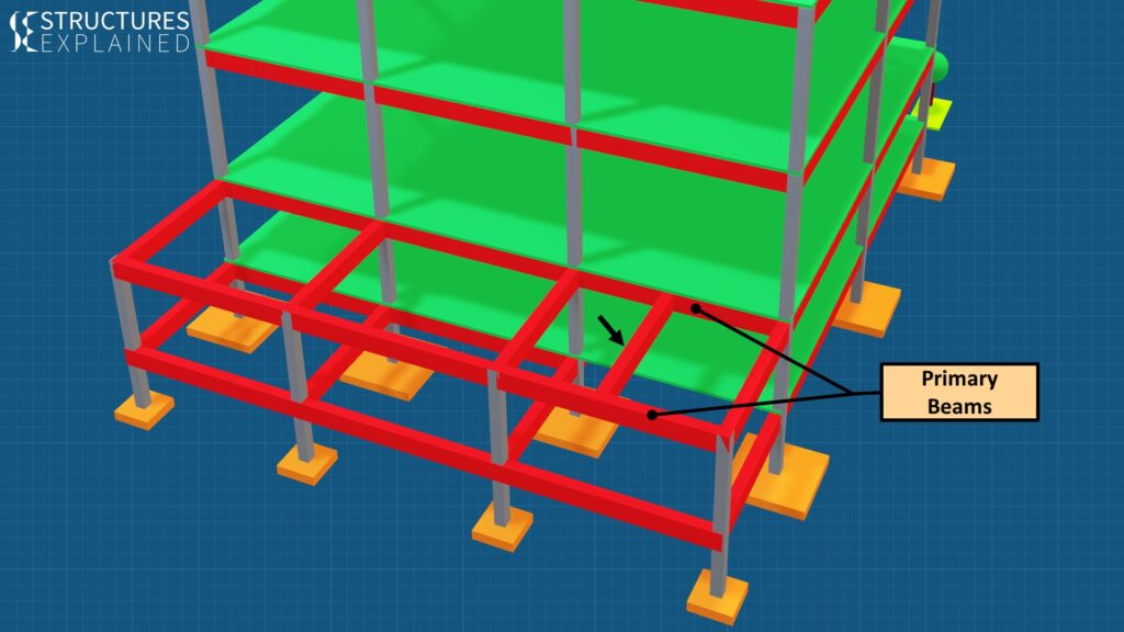
Third kind of beams which get the torsion forces are the primary beams which support the secondary beam resting on them. These beams are main contenders to get torsional reinforcement due to the loading from one side.
Needless to say, these beams require thorough analysis for their design to resist various forces acting on them.

Torsional forces will also be applicable in the whole building when acted by an earthquake. When the centre of rigidity and centre of mass of the building does not match with each other eccentric forces will develop twisting the whole building.
Watch the below video to see the animations for better understanding.




Pingback: buy rybelsus online
Pingback: clomid buy online
Pingback: cialis soft
Pingback: cialis manufacturer coupon 2021
Pingback: sildenafil citrate tablets ip 50 mg
Pingback: ginseng root tea for stamina
Pingback: 80mg cialis
Pingback: viagra 25 mg for sale
Pingback: viagra 50 mg tablet
Pingback: canadian pharmacies cialis
Pingback: 50 off viagra
Pingback: pill cialis